Project planning guide
Before you build
Use the reference image and planning notes as a starting point. Confirm dimensions, loads, materials, local codes, and site conditions before purchasing or cutting.
- Wood and Steel Furniture
- 6 reference images
- Print-friendly guide
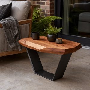
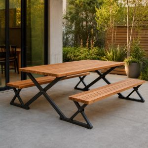
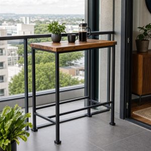
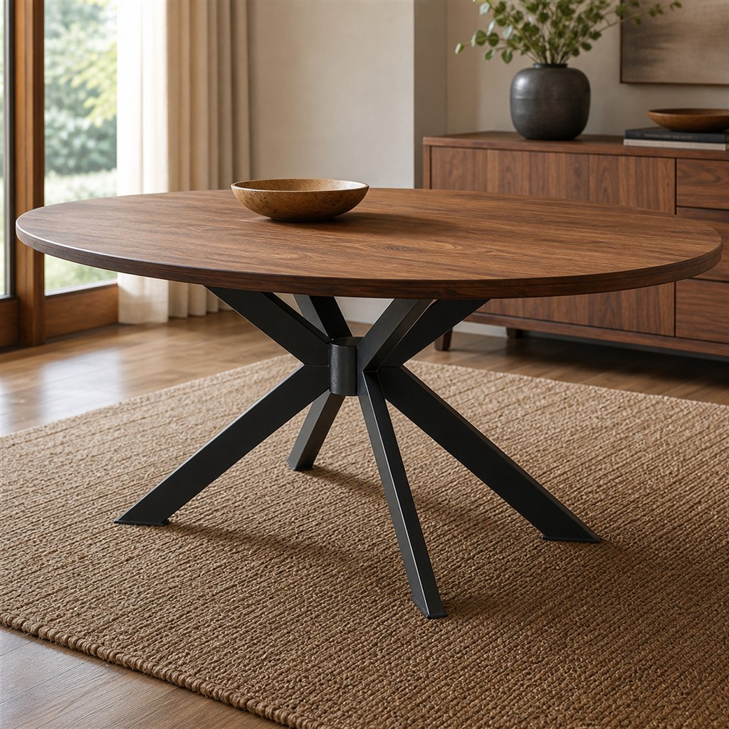
Oval Walnut Dining Table With a Sculpted Spider Base is an original furniture concept intended to seat family and guests around a stable surface while making the wood top and steel base read as one balanced design. The most refined wood-and-steel furniture often looks simple because its clearances, attachment points, finish sequence, and load paths were settled before either material was cut. The dimensions and material selections below are planning references, not shop drawings or engineering. Confirm the actual room, users, loads, wood moisture, steel section, hardware, and fabrication method before construction.
Quick answer: Start near about 60 inches round and 30 inches high, using kiln-dried walnut with powder-coated rectangular steel tube. Plan the frame to leave deliberate knee clearance and connect the top through slotted plates that permit seasonal wood movement. The most important precaution is to have steel fabrication and weld design reviewed or performed by a qualified fabricator, isolate hot work from wood and finishes, and test stability under realistic loads.
Design concept at a glance
| Furniture concept | a carefully fabricated oval walnut dining table with a sculpted spider base |
|---|---|
| Suggested setting | a warm contemporary dining room |
| Planning envelope | about 60 inches round and 30 inches high |
| Wood direction | kiln-dried walnut |
| Steel direction | powder-coated rectangular steel tube |
| Primary design load | distributed dining loads plus the leverage created when someone presses on an edge |
| Interface priority | leave deliberate knee clearance and connect the top through slotted plates that permit seasonal wood movement |
| Finish direction | a low-sheen protective wood finish paired with a fully cured corrosion-resistant steel coating |
Begin with use, placement, and circulation
Mock up the full envelope in a warm contemporary dining room before settling the frame. Tape the footprint on the floor and use boxes or temporary rails to represent the top, seat, shelves, doors, or drawers. Approach it from every normal direction. Check door swings, chair movement, baseboards, outlets, cleaning access, robot vacuums, rug edges, sunlight, heating vents, and the route required to carry the finished piece into the room.
Dining furniture needs generous knee and chair clearance, predictable edge overhang, and a base that remains comfortable from every seat. Confirm that the steel geometry does not create shin contact or trap chair legs. Measure the real objects the furniture must support. Add clearance for hands, cables, upholstery, dishes, books, media equipment, or storage bins rather than designing around an empty rendering. Photograph the mock-up and record every changed dimension so the fabrication drawings reflect the final decision.

Set proportions from a direct load path
about 60 inches round and 30 inches high is a useful starting envelope. Draw the wood and steel as separate structural systems, then trace how distributed dining loads plus the leverage created when someone presses on an edge travels to the floor or wall. Tops and seats span between supports; shelves push outward on frames; open drawers create leverage; and someone leaning at a corner can twist a frame that appears strong under centered weight. Avoid thin visual members that cannot resist the actual bending, racking, and connection forces.
Place the steel supports far enough apart to control wood span but not so wide that feet or glides sit at vulnerable corners. Check the support polygon in plan view and verify that the center of mass remains within it under foreseeable loading. If the piece is tall, narrow, wall-mounted, foldable, extendable, mobile, or used for seating, obtain appropriate professional review and test a full-scale prototype gradually.
Coordinate wood selection and movement
The concept uses kiln-dried walnut. Buy material with moisture appropriate to the intended interior or protected exterior environment, then allow it to acclimate according to supplier and professional guidance. Mill in stages when possible so internal stress can show before final sizing. Keep structurally important rails and edges free from splits, severe grain runout, loose knots, or unsupported short grain.
Solid wood normally changes width across the grain as moisture conditions change. A rigid steel perimeter does not move the same way. Wide tops, seats, and panels therefore need a connection strategy that restrains lifting and sliding while allowing controlled cross-grain movement. Veneered plywood can be more dimensionally stable for cabinet cases, but edge details, fastener holding, and veneer durability still need attention.
Develop the steel frame as real fabrication
The steel direction is powder-coated rectangular steel tube. Draw the actual tube, angle, flat bar, rod, or plate thickness rather than a symbolic line. Resolve miters, bend radii, cap plates, access for tools, weld zones, threaded features, floor glides, and drainage or vent holes where enclosed members or outdoor exposure require them. Ask the fabricator what tolerances and finishing allowances are realistic before freezing the wood dimensions.
A credible connection direction is square, cleanly dressed welded joints or manufacturer-rated mechanical connectors sized by a qualified fabricator. Weld size, joint preparation, distortion control, and capacity are project-specific engineering and fabrication decisions. Do not treat a decorative tack, an unverified adhesive bond, or a screw placed into thin unsupported metal as a structural connection. Keep sharp corners, burrs, open tube ends, and proud weld spatter away from users, floors, upholstery, and wiring.
Plan the wood-to-steel interface
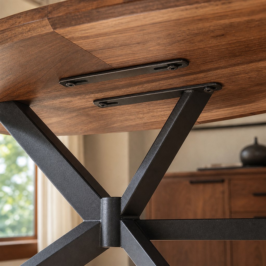
The interface should use threaded inserts or figure-eight/slotted fasteners arranged to allow seasonal movement without splitting the top. Mounting plates need enough bearing area to avoid crushing the wood, while slots or movement hardware need the correct orientation to permit cross-grain change. Washers, shoulders, spacers, or bushings may be required so tightening a fastener does not clamp a moving slot permanently or pull a thin steel tab out of plane.
Keep steel slightly separated from vulnerable finished surfaces when abrasion, trapped moisture, or finish damage is possible. Test the entire attachment sequence with sample material, including drill size, insert installation, screw length, washer stack, torque, and future tool access. A hidden fastener is not serviceable if the furniture must be destroyed to reach it.
Create coordinated shop drawings
Prepare a dimensioned plan, elevations, sections, and an exploded interface detail. Use one datum system for the wood parts and another for the steel frame, then identify the dimensions that connect those systems. Mark finished dimensions rather than assuming nominal lumber or tube sizes. Include floor variation, glide adjustment, top flatness, door and drawer reveals, and the clearance needed to apply finish.
Make separate schedules for wood parts, steel parts, hardware, and finishes. The wood schedule should include species, grain direction, finished size, quantity, edge treatment, and joinery. The steel schedule should identify section, wall or plate thickness, length, angle, bend, hole, thread, cap, weld symbol or connector, and finish. Have a qualified person review drawings that control structural capacity, seating safety, wall attachment, moving mechanisms, or public use.
Prototype critical geometry before final fabrication
Build a full-size mock-up of at least one corner, leg, seat, mounting plate, drawer opening, or moving mechanism. Inexpensive plywood, hardboard, and screwed wood strips can reveal proportion and access problems before steel is cut. Test knee, toe, hand, cable, and cleaning clearance. Verify that clamps, drivers, wrenches, and finish applicators can reach their work without scratching adjacent surfaces.
For repeated legs or frames, use a fabrication fixture designed by the qualified fabricator, but allow for heat distortion and finishing buildup. For wood, use story sticks and matched setups to keep corresponding holes and edges consistent. Measure the completed steel frame itself before drilling a valuable top; fabrication reality should control the final interface holes.
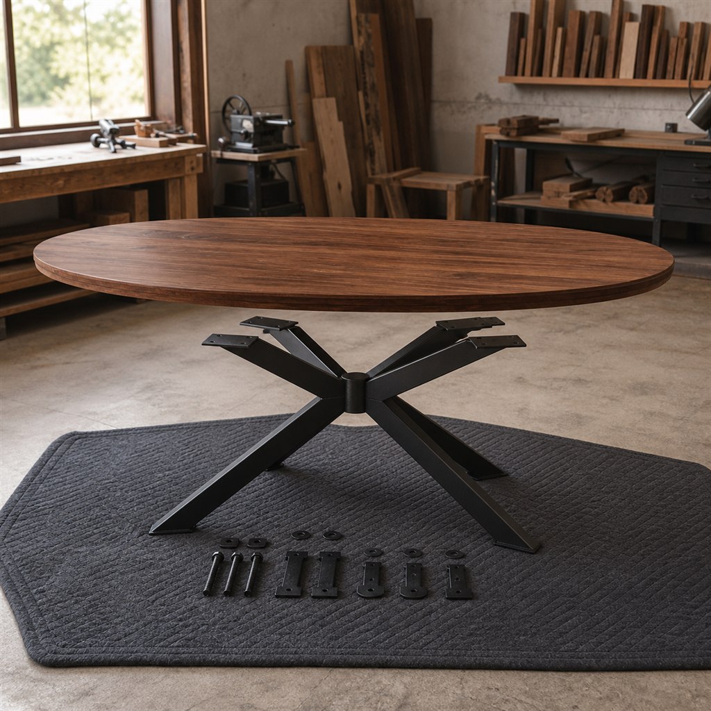
Use a safe, separated fabrication sequence
- Confirm drawings and samples. Approve material, finish, edge profile, steel section, glides, and connection hardware.
- Fabricate the steel away from wood. Qualified personnel complete cutting, drilling, bending, welding, dressing, cleaning, and inspection in an appropriate metalworking area.
- Dry-check the steel frame. Verify flatness, square, rocking, hole access, and actual dimensions before coating.
- Mill and join the wood. Prepare parts from stable stock, preserving grain direction and planned seasonal movement.
- Dry-assemble the interface. Use sample fasteners and temporary protection to confirm slots, clearances, and tool access.
- Finish materials separately. Complete steel coating and wood finishing under their product instructions, then allow full cure.
- Assemble and test gradually. Protect finished surfaces, tighten hardware appropriately, level the piece, and apply representative loads in controlled steps.
Control hot-work, fume, and fire hazards
Do not weld, grind, or cut steel beside stored lumber, sawdust, solvent, finish, upholstery, or other combustible material. OSHA hot-work guidance emphasizes removing or shielding combustibles, providing suitable fire protection, and controlling sparks and heat. Welding and cutting can also create hazardous fumes, ultraviolet radiation, noise, and hot surfaces. The required controls depend on the material, coating, process, workplace, and local rules.
The project-specific rule remains: have steel fabrication and weld design reviewed or performed by a qualified fabricator, isolate hot work from wood and finishes, and test stability under realistic loads. Never weld coated, plated, painted, unknown, or contaminated steel without identifying the material and establishing appropriate professional controls. Do not use oxygen for ventilation or cleaning. HomeBuildPlans.com does not provide welding procedure specifications, structural weld design, ventilation design, respiratory selection, or hot-work authorization.
Prepare and finish both materials separately
The finish direction is a low-sheen protective wood finish paired with a fully cured corrosion-resistant steel coating. Sand and prepare the wood through a consistent sequence, ease handling edges, and test color on offcuts from the same board. Keep finish out of threaded inserts, movement slots, glue surfaces, and hardware seats. Confirm suitability for the expected contact, cleaning products, heat, moisture, food service, children, pets, or outdoor exposure.
Steel preparation and coating should follow the coating supplier and fabricator’s requirements. Remove fabrication residue, sharpness, oil, and contamination by an appropriate controlled process. Account for coating thickness at sliding fits, threaded parts, and tight reveals. Let both materials cure fully before assembly so pads and mounting plates do not imprint or bond unintentionally to soft finishes.
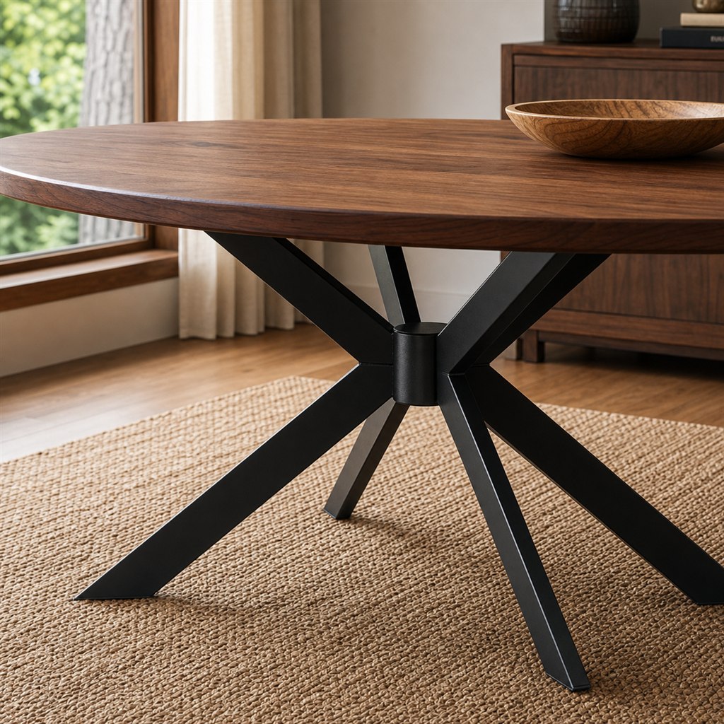
Check stability, anchoring, and user contact
The main design load is distributed dining loads plus the leverage created when someone presses on an edge. Place the finished piece on the least favorable expected floor and check every glide or foot. Apply load gradually at the center, edges, corners, shelves, doors, drawers, seat, back, or foot rail as relevant. Stop if the frame rocks, deflects unexpectedly, cracks, loosens, or lifts a foot. A passing visual inspection is not a rated load test.
Tall or climbable storage deserves particular caution. Follow current CPSC furniture tip-over guidance and use an appropriate anchoring system connected to verified building structure. Keep heavy objects low and avoid placing tempting objects where children may climb. Wall-mounted and overhead pieces require connectors and structure appropriate to the substrate and load, not generic anchors selected by appearance.
Plan inspection and long-term maintenance
Inspect the furniture after the first weeks of use and at regular intervals. Look for loose fasteners, elongated holes, crushed wood fibers, cracked joints, finish wear, corrosion, rocking, glide damage, drawer misalignment, and changes in top flatness. Seasonal movement can alter reveals and fastener position even when the original construction was correct.
Clean wood and steel with methods approved for their respective coatings. Do not allow water or cleaning solution to collect at the interface. Replace damaged glides and pads before steel scratches the floor. If a weld cracks, a structural member bends, an anchor loosens, or a moving mechanism binds, stop using the piece and have it evaluated rather than hiding the symptom with cosmetic repair.
Planning checklist
- Mock up about 60 inches round and 30 inches high in the intended room and test circulation, reach, and transport.
- Trace distributed dining loads plus the leverage created when someone presses on an edge through the wood, interface hardware, steel frame, and floor or wall.
- Document actual kiln-dried walnut moisture, grain direction, joinery, and movement allowance.
- Specify the real powder-coated rectangular steel tube section, connection, access, finish, feet, and tolerances.
- Plan to leave deliberate knee clearance and connect the top through slotted plates that permit seasonal wood movement.
- Prototype a full-size corner or interface before final wood and steel fabrication.
- Keep hot work completely separated from wood, dust, solvents, and finishes.
- Test stability and function gradually; anchor tall or climbable furniture appropriately.
Frequently asked questions
Can the example dimensions be changed?
Yes. Treat about 60 inches round and 30 inches high as a planning reference. Recheck spans, clearances, center of mass, steel section, connection capacity, and furniture stability whenever dimensions or materials change.
How should a solid-wood top attach to steel?
The attachment normally must hold the top securely while permitting expected cross-grain movement. Slotted steel plates, appropriate tabletop fasteners, or other engineered details may work when oriented and installed correctly. The final solution depends on grain direction, width, moisture range, hardware, and frame geometry.
Can welding be completed beside the woodworking area?
Hot work should be separated from lumber, dust, finishes, solvents, and other combustibles, with controls appropriate to the process and workplace. Use qualified fabrication services when the space, equipment, ventilation, fire protection, or experience is not suitable.
Does a heavy steel base guarantee stability?
No. Stability depends on footprint, center of mass, load position, floor contact, frame stiffness, anchors, and user behavior. A heavy narrow base can still tip, rack, or damage a floor.
Editorial disclosure: This article and its six original conceptual images were created for design and planning inspiration. HomeBuildPlans.com does not sell measured drawings, furniture, steel fabrication, welding services, structural engineering, load certification, or installation for this concept.