Project planning guide
Before you build
Use the reference image and planning notes as a starting point. Confirm dimensions, loads, materials, local codes, and site conditions before purchasing or cutting.
- Woodworking
- 1 reference image
- Print-friendly guide
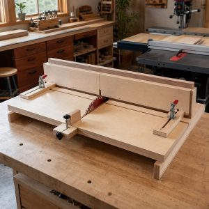
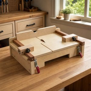
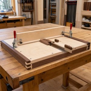
Hand-Saw Miter Box With Replaceable Kerf Guides is an original concept designed to improve repeatable layout, cutting, squaring, or glue-up without placing hands near an exposed cutting edge. A useful jig, shop fixture, or furniture piece should be stable, serviceable, and understandable at a glance. The concept below is a starting point to measure and prototype in the real workspace. The example dimensions and materials are planning references rather than a measured plan. Verify every dimension, fastener, load path, tool interface, and clearance against the actual build before cutting.
Quick answer: Begin around about 24 inches wide, 16 inches deep, and 6 inches high. Use flat cabinet-grade plywood, dimensionally stable hardwood runners, replaceable fences, mechanical clamps, and clearly visible stop blocks, and plan to reference every cut from a straight fence and positively restrain the work without trapping offcuts against the blade. The main precaution is to retain guards and riving devices, provide safe hand clearance, support the full workpiece, and never use a jig that binds or crosses the cutting path unpredictably.
Project concept at a glance
| Project | a carefully built hand-saw miter box with replaceable kerf guides |
|---|---|
| Suggested setting | a clean table-saw workstation |
| Planning envelope | about 24 inches wide, 16 inches deep, and 6 inches high |
| Material direction | flat cabinet-grade plywood, dimensionally stable hardwood runners, replaceable fences, mechanical clamps, and clearly visible stop blocks |
| Joinery direction | laminated fences, captured runners, replaceable inserts, and bolted stops |
| Key design priority | reference every cut from a straight fence and positively restrain the work without trapping offcuts against the blade |
| Primary precaution | retain guards and riving devices, provide safe hand clearance, support the full workpiece, and never use a jig that binds or crosses the cutting path unpredictably |
Define the real job before drawing the project
Write down what the project must hold, guide, store, or support during normal use. For a cutting and layout workflow, identify the starting position, every adjustment, the direction of force, the finished position, and how the work will be removed. A fixture that looks compact in a sketch can become awkward once a clamp handle, dust hose, drawer, door, or long board must move through its full range.
Set the concept in a clean table-saw workstation and mark its footprint with scrap strips or painter’s tape. Bring the actual workpiece, accessories, and personal protective equipment to the mock-up. Check approach space, lighting, outlets, cord and hose routes, standing position, and where offcuts or removable parts will go. Furniture should be checked against doorways, baseboards, outlets, seating clearance, and cleaning access. A shop fixture should be checked against infeed, outfeed, guarding, and emergency shutoff access.
Confirm dimensions from reference surfaces
about 24 inches wide, 16 inches deep, and 6 inches high is only a useful starting envelope. Establish one reliable face and one reliable edge, then dimension guides, fences, drawer openings, or hardware locations from those references. Avoid chains of small measurements that compound error. For tool-related projects, use the manufacturer’s table, base, fence, insert, mounting holes, and specified operating clearances as the controlling geometry.
Make a full-size section from cardboard, hardboard, or inexpensive plywood wherever hands, hardware, or moving parts meet. Test grip clearance with the largest expected workpiece. Allow wood drawers and doors to move through seasonal humidity changes, but do not add unmeasured looseness to a jig that depends on repeatability. Record the prototype changes on the drawing rather than relying on memory.
Choose wood and sheet goods for the job
The suggested palette is flat cabinet-grade plywood, dimensionally stable hardwood runners, replaceable fences, mechanical clamps, and clearly visible stop blocks. Flatness and stability often matter more than decorative grain in a jig or cabinet interior. Use clean, sound material around narrow webs, fasteners, hinges, handles, and clamping points. Reject parts with splits, severe twist, loose knots, or damaged plies where the load concentrates. Orient solid wood so predictable seasonal movement does not jam a captured panel or split a rigid cross-grain connection.
Use the USDA Forest Products Laboratory Wood Handbook as a technical reference for wood movement, mechanical behavior, adhesives, fasteners, and finishing. It is not a project-specific design approval. Confirm the rating and instructions for every screw, anchor, caster, slide, hinge, adhesive, finish, magnet, and electrical accessory used in the final build.
Prepare a cut list and joinery map
Break the project into primary structure, reference surfaces, moving components, replaceable wear parts, and cosmetic trim. A useful cut list records finished length, width, thickness, quantity, material, grain direction, reference face, and edge treatment. Add setup pieces and test stock. Mark which dimensions must match as a group instead of cutting each part from an isolated measurement.
The likely joinery direction includes laminated fences, captured runners, replaceable inserts, and bolted stops. Choose joints according to the force: racking, withdrawal, shear, bending, or repeated adjustment. Dry-fit the primary frame and measure diagonals before fixing panels that lock it square. Keep critical fences and guide rails adjustable until a real test confirms alignment. Sacrificial inserts, runners, pads, liners, and bushings should be replaceable without destroying the main assembly.
Lay out controls, clamps, and hardware
Place adjustment knobs and clamp handles where they can be reached without crossing a blade, bit, pinch point, or loaded component. A clamp must resist the direction of cutting or working force, not merely press the piece downward. Stops need enough bearing area to remain square after repeated contact. Slots and pivots require washers or bearing surfaces that prevent soft wood from crushing as hardware is tightened.
For furniture, support slides, hinges, lid stays, cleats, and wall anchors with continuous material rather than a thin decorative edge. For mobile shop fixtures, choose casters for the actual loaded weight and floor condition, then provide a positive way to prevent movement during use. Tall storage should be anchored appropriately, and heavy objects should stay low. Never assume a wall covering alone can carry a mounted project; locate and verify suitable structure.
Build in a controlled sequence
- Mill and label reference parts. Prepare the straightest base, fence, rails, or case sides first and mark their reference faces.
- Build the primary structure. Assemble the load path, check square and flatness, and correct twist before adding secondary parts.
- Install guides and hardware. Use setup blocks or templates so paired parts align, but leave planned adjustment available.
- Add workholding and stops. Test clamp range, handle travel, and positive retention with the power disconnected.
- Fit wear components. Install sacrificial fences, inserts, pads, dust fittings, liners, or trays so future replacement is straightforward.
- Ease and finish surfaces. Break sharp handling edges, protect vulnerable end grain, and keep finish out of glue surfaces and precision-running fits.
- Test gradually. Begin unloaded or with scrap, apply force in small increments, and stop immediately if any part shifts, binds, vibrates, or loosens.
Preserve guarding and safe workholding
The project-specific rule is to retain guards and riving devices, provide safe hand clearance, support the full workpiece, and never use a jig that binds or crosses the cutting path unpredictably. A homemade jig must never defeat a required guard, riving knife, anti-kickback feature, trigger behavior, interlock, or manufacturer-specified mounting method. If a portable tool is not designed to be fixed into a stand, do not improvise a clamp around its body or trigger. Contact the manufacturer or use a purpose-built listed accessory.
OSHA’s machine-guarding overview identifies point-of-operation, rotating-part, flying-chip, anchoring, and eye-protection hazards, while 29 CFR 1910.213 addresses woodworking machinery in workplaces. Home shops may be governed differently, but the hazard-control principles are useful. Always follow the current tool manual and applicable workplace or local rules.
Control dust, noise, and finishing exposure
Plan dust pickup at its source without narrowing a guard opening or creating a snagging hose loop. Fine dust can escape even when chips appear captured, so combine suitable extraction with ventilation and housekeeping. Do not use an ordinary vacuum for hazardous or combustible material unless it is specifically rated for that use. Keep dust collection separate from ignition sources and follow the equipment manufacturer’s filter, grounding, and disposal instructions.
Use eye and hearing protection appropriate to the operation, and select respiratory protection according to the material, finish, exposure, and current instructions. Read safety data and product labels before using adhesives, solvents, finishes, treated wood, or unfamiliar sheet goods. Oily finishing materials can create a fire hazard; store and dispose of applicators exactly as the finish manufacturer and local fire authority direct.
Check ergonomics and failure modes
Stand at the mock-up and repeat the full task slowly. Avoid a design that requires leaning across the work, lifting a heavy part above shoulder level, holding a component with one hand while tightening with the other, or looking away from a moving tool to find a control. Handles should be large enough for a secure grip, and sharp corners should not occupy knee, hip, or walking space.
Ask what happens if a knob loosens, a board catches, a drawer opens, a caster unlocks, a wall anchor misses structure, or a user loads the project from one corner. Design a benign response with positive stops, restrained moving parts, broad support, or redundant attachment where appropriate. Decorative elements should not be mistaken for braces, and friction alone should not secure a heavy or hazardous moving assembly.
Accuracy and maintenance checks
Before first use, confirm the base is stable, fences are straight, runners move without side play, fasteners are tight, and clamps hold representative scrap against the expected force. For a jig, make a shallow or low-risk test on scrap and inspect the result before progressing. For furniture or storage, load gradually and watch joints, anchors, slides, and casters rather than jumping directly to the intended maximum.
Inspect the project regularly. Dust and finish buildup can change a precision fit; repeated clamping can crush wood fibers; humidity can move solid wood; and vibration can loosen unrestrained hardware. Replace damaged inserts, pads, runners, cords, or fasteners promptly. Stop using the project if it rocks, cracks, binds, loses alignment, exposes a sharp part, or interferes with a safety feature.
Planning checklist
- Define the operation, workpiece range, load, and complete movement before choosing dimensions.
- Measure the actual tool, hardware, room, or mounting structure rather than relying on nominal sizes.
- Plan to reference every cut from a straight fence and positively restrain the work without trapping offcuts against the blade.
- Choose flat cabinet-grade plywood, dimensionally stable hardwood runners, replaceable fences, mechanical clamps, and clearly visible stop blocks and verify compatibility among wood, fasteners, adhesives, and finish.
- Map laminated fences, captured runners, replaceable inserts, and bolted stops to the real racking, shear, bending, and withdrawal forces.
- Preserve required guards, clear emergency controls, and positive workholding.
- Prototype critical clearances and make the first test with scrap and minimal load.
- Document alignment points, replaceable wear parts, and a regular inspection routine.
Frequently asked questions
Can the example dimensions be changed?
Yes. Treat about 24 inches wide, 16 inches deep, and 6 inches high as an envelope for planning. Base final dimensions on the actual tool, workpiece, room, hardware, and user. Recheck stability, spans, fastener loads, and guarding whenever the project grows taller, wider, longer, or heavier.
Is plywood or solid wood better?
Stable plywood is often useful for broad jig bases, cabinet cases, and flat reference surfaces. Solid wood can provide durable edges, runners, handles, and visible furniture parts. Either can fail if its grade, grain, thickness, joinery, or moisture movement is ignored, so choose by function rather than appearance alone.
Can a shop-built jig replace a machine guard?
No. A jig can improve positioning or workholding, but it does not automatically qualify as a guard and must not defeat required protection. Retain manufacturer safety equipment and instructions. Guard design for hazardous machinery should be reviewed by a technically competent, qualified person.
How should the finished project be tested?
Test alignment and movement with power disconnected, then use scrap and the lowest practical load or depth. Stand outside likely ejection paths, keep others clear, and stop at the first sign of movement, vibration, binding, overheating, cracking, or hardware loosening.
Editorial disclosure: This article and its original conceptual image were created for planning inspiration. HomeBuildPlans.com does not sell a measured plan, jig, tool, product, installation service, certification, or engineering for this project.